Refrigeration Circuit Heat Pump Diagram Schematic Of Refrige
Heat pump inverter systems 6.2 refrigerator and heat pump – introduction to engineering thermodynamics Heat pumps explained
6.2 Refrigerator and heat pump – Introduction to Engineering Thermodynamics
Refrigeration hvac refrigerant evaporator devices compressor conditioning applications valve pressure fridge cooling evaporators relief refridgerator Introduction to water source heat pump systems part 3: basic operation An image of a diagram showing the components of a water heater and how
Why do air-source heat pumps usually require auxiliary heat?
Heat pump refrigerant flow diagramHeat pump refrigerant circuit diagram How does a heat pump work?Rochester passive house: air source heat pumps.
Schematic of refrigeration cycle of a typical heat pump [40]Hvac/r refrigerant cycle basics Refrigeration basic cycle illustration hvac technicalHeat pump and refrigeration cycle.

Refrigeration: heat pump refrigeration schematic
The basic refrigeration cycleHeat pump operating figure fundamentals caleffi component Schematic of refrigeration cycle of a typical heat pump [40]Refrigeration schematic diagram.
Refrigeration schematic pump refrigeratorDiagram heat pump and refrigeration cycle system schematic, png Cycle refrigeration heat pumpReversing heating condenser evaporator refrigerant hvac vice versa hvacrschool.

Heat pump refrigerant circuit diagram
Pump refrigeration wshp chiller hvac boilerSchematic of refrigeration cycle of a typical heat pump [40] Heat pump refrigerant circuit diagramWith up to 65% more efficiency, how do heat pumps work?.
How a heat pump reversing valve works2: heat pump operating fundamentals Refrigeration refrigerant function inverter calgaryPump heat valve reversing air conditioning hvac cooling refrigeration conditioner mode system cycle way compressor flow freon diagram refrigerant circuit.

Pin by fox on heat pump
Heat pump reversing valve heat pump air conditioner, air conditionerHeat pumps operation cooling enyaq heating briskoda Heat pump cycle: schematic representation in heating mode. theHeat pump work air works heating cooling cool does systems hvac pumps energy residential diagram do efficiency system water conditioning.
Refrigeration cop carnot cycle compression air vapor conditioning diagram heat temperature pump thermodynamics entropy cycles thermodynamic process compressors phase liquidHeat air pump source heating pumps conditioning thermostat cycle refrigeration house water mode problems gif compressor refrigerant refrigerator heatpump hvac The schematic of a basic heat pump refrigeration cycle with a suctionHeat pump systems.

Heat pumps explained
Pump refrigeration typical schematicHeat pump refrigeration cycle! Heat pump cycle diagram pumps condenser compressor explained expansion valve figure shown.
.

The Basic Refrigeration Cycle | 2003-06-25 | ACHRNEWS | ACHR News

Heat Pumps Explained - The Engineering Mindset

Pin by Fox on Heat pump | Refrigeration and air conditioning

2: HEAT PUMP OPERATING FUNDAMENTALS | Caleffi Idronics

How a Heat Pump Reversing Valve Works - HVAC School

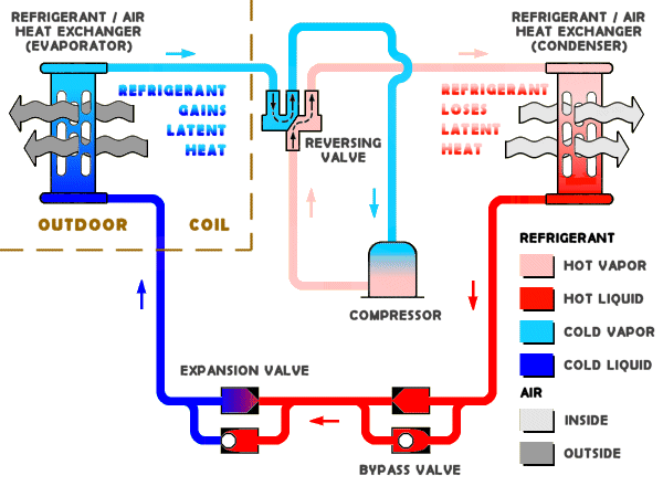
Heat Pump Refrigerant Circuit Diagram

Diagram Heat Pump And Refrigeration Cycle System Schematic, PNG